ICPDAS STEP-200
2-Axis Stepping Motor Control Card
| Odering
Information
STEPPER-200 : 2-Axis
Stepper Motor Control Board Option : DN-25: 25-pin
Screw Terminal Board
|
Features & Specifications
|
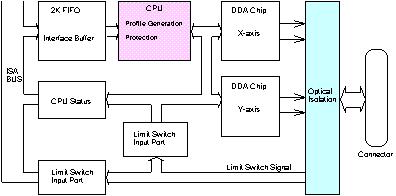 |
| STEP-200 is a two axes commanded-based Stepping motor control card. It can be used in pulse-type servo motor control card. It equipped a 2Kbytes-FIFO. FIFO is used to receive motion command from host PC. The ŁgP is used to generate profile and control the mechanism of protection. The two DDA chips is used to execute DDA function when interpolation command is executed.. The 2500Vrms optical isolation is designed for industrial application. |
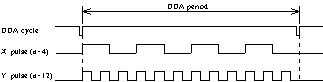 |
| The DDA chip is the heart of STEP-200 , it generate equal-space pulse train corresponding to specified pulse number during a DDA period. This mechanism is very useful to execute pulse generation and interpolation function. The DDA period can be determined by DDA cycle. Table(1) shows the relation among DDA cycle, DDA period and output pulse rate. When DDA cycle is set to 1, the DDA period is equal to 8.192ms. The output pulse number can be set to 0~2047, therefore the maximum output pulse rate will be 249.877kpps. The minimum output pulse rate is 0.96pps when set DDA cycle=254 (DDA period = 1040.384ms). |
| DDA cycle | DDA period | Max. pulse rate(n=2047) |
Min. pulse rate(n=1) |
| 1 | 8.192ms | 249,877pps | 122pps |
| 2 | 12.288ms | 166,585pps | 81pps |
| 3 | 16.384ms | . | . |
| . | . | . | . |
| N | (N+1)*4.096ms | 2,047/(DDA period) | 1/(DDA period) |
| . | . | . | . |
| 254 | 1040.384 | 1,967pps | 0.96pps |
| The DDA cycle can be set by MSTEP2_SET_VAR(DDA_cycle,
Acc_Dec, Low_Speed, High_Speed) command which decribed in
charpter 3. The selection criterion of DDA cycle is
described as the following. (1) The required max. output pulse rate. PRmax : max. output pulse rate. 2. The required speed resolution. 3. Large DDA cycle (DDA period), it will generate
vibration between different pulse input which generally
can be observed during acceleration or deceleration. So,
the small DDA cycle , the smooth acceleration/deceleration
curve as long as the speed resolution can be acceptable. |